The Autotron Manual
Automatic register systems were used at Sun Engraving as early as the beginning of the 1930s, but more widespread use of this technology had to wait for the Second World War, which brought dramatic developments – through radar and computing – to the field of electronics. The Autotron was developed in the 1950s by Crosfield and Sons, with Sun Printers, and was field tested and put into full production use at the Sun. It became the first off-the-shelf system to permit the automatic control of colour register on large gravure presses, and after its introduction at the Sun it was successfully used throughout the industry.
Alan Hoare wrote the first User Manual at the Sun for the Autotron, and this is it.
THE AUTOTRON: DETAILS AND INSTRUCTIONS AS TO ITS USE
AN ELECTRONIC APPARATUS that converts light impulses into electrical energy, by means of the photo electric cells, which is amplified so as to operate the register control motors.
Power Pack – Base of Cabinet
This section of the equipment takes the first input of mains power and divides it into smaller voltages as needed by the rest of the equipment.
Output Chassis
These are situated immediately above the power pack and take the final impulses that make the corrections to the register motors, having in their circuits magnetic contacts that make the advance or retard alterations.
Input Chassis
These sections are virtually the heart of the equipment and sort out all the smaller impulses from the magnetic switches and scanning heads, etc.
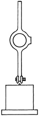
Scanning Heads
The most delicate part of the equipment and should be handled with utmost care. They house the two photocells; a valve to amplify the very small current emitted from them, a 12v., l8w. lamp similar to a car headlamp, but having a vertical filament that shines through a prism and directs two bars of light half an inch by one-sixteenth of an inch on to the paper.
Magnetic Switch
A mechanical method of switching the impulses from the scanning head on and off either side of the register lines printed on the paper.
Control Panel
This enables the equipment to be operated manually allowing the current to be induced to the motor or motors as long as the operating switch is depressed and also for switching over to automatic. Controls to compensate for “split register shift” due to faulty processing should the particular job warrant it are on this panel together with meters that indicate the amount of register error at any time.
Oscilloscope Tester
A test instrument built into the cabinet designed chiefly to check the synchronization of s/heads and magnetic switches. It will also indicate some faults that may develop in the equipment.
Register Lines
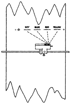
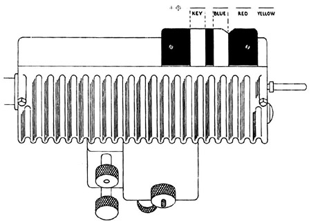
These lines etched on the cylinders should follow the correct sequence. Standing in front of the web the colours should read left to right; key, blue, red and yellow (see illustration).
Setting Magnetic Switch
SETTING UP
Run the first reel on ordinary register control so as to allow the press to settle down. Particular care should be taken to see the lateral register is right before making the Autotron adjustments.
The s/heads are then centred on to the register lines concerned, i.e. (R & Y) (B & R) or (K & B). On the top of each s/head is a small black plate with two white lines (one and a half inches by half an inch) painted on and these two white lines should be accurately lined up opposite the register lines (see illustration).
Method of Setting Up
Crawl machine with pressure down and hold a black crayon on web on roller below scanning head, so that it makes a line dead between the two register lines. Sight scanning head so that the light bars are one each side of this line. This does not apply to the yellow or first colour which has no scanning head, and this cylinder can be moved with impunity. On V.2 Vomag units, the cylinders have no register motors and the switch has no adjustment for use on the run. If cylinders are off the switch slightly a small adjustment can be made by slackening the arms which hold the scanning head bar and moving scanning head up or down in relation to the web. Moving scanning head towards cylinder has the same effect as advancing cylinder. The auto register on Vomag units only have about 3-inch movement and should be set centrally before starting up. This should, of course, be done whilst getting ready, and ordinary machine tension rollers used for the first positioning.
MAGNETIC SWITCH
Crawl machine with pressure down and stop when register line is dead in line with light bar. This will mean a certain amount of inching. It is usually preferable to stick a small strip of gummed tape along register line to make it more easily seen. When setting red cylinder use the red line, not the yellow; blue cylinder, blue line and so on. When cylinder is in position, set magnetic switch. On No.6 and similar machines switch is set by turning bakelite knob behind switch unit until pointer is in line with scribed line on rotating disc. If the line has a 1 scribed on it, No.1 pointer must be set opposite. If the line has a 2 scribed on it, No.2 pointer must be used, etc. This is important. Once these positions have been correctly set the cylinder register buttons must not be moved as they put cylinders out of time with switch. Care must be taken when turning these pointers that the flexible lead coiled round shaft in casing is not wound up tight, otherwise ends of wire are pulled out of their sockets and a broken contact is the result. Conversely, the lead must not be unwound too loosely or it may jam in the rotating magnet. These cases have occurred. On the older type of switch such as V.2 the rotating magnet is held in its spindle by a grub-screw.
TO SET OLDER TYPE
Loosen grub-screw and set rotating magnet so that the two pole pieces are exactly one each side of the knife edge on the large electric magnet (see illustration).
To Set Older Type
Make certain that all back-lash is taken up before tightening grub-screw. The machine can then be “run up” to normal speed B preferably over 5,000 revs. – the register brought in manually on the Autotron control panel, the metres being ignored until a register error of less than 25 thou. is indicated. When this error shows a tendency to lessen, the equipment can be switched over to “Auto” with confidence.
REGISTER SHIFT
When all the needles are at zero any register corrections for bad fit can be made; the small toggle switch moved to the advance or retard position, the dial set to the amount of error judged to be necessary. The needle on the dial will be observed to move to the error set on the dial and then immediate compensation will take place and a zero reading will be observed again. When a machine is at rest the register error will show on the appropriate dial. Register corrections are made approx. every 10 revs. but this can be adjusted if considered necessary by a control low down in the base of the power pack – this should however not be done by the minder but by the engineer.
TESTING WITH OSCILLOSCOPE TESTER
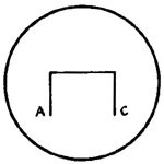
These testers give a perfect test for the positioning of magnetic switches. With machine running, switch on test-unit and plug test lead into unit to be tested. The resultant screen picture should look something like this. (See Fig. 1 below.)
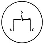
Starting from left to the first rise A denotes point at which switch comes into operation and C the point where it switches off. The peak or small depression – is the position of the register line in relation to the switch. It should be dead central; if peak is to the left, cylinder needs retarding or switch needs turning anti-clockwise, if to the right the reverse is the case.
Most of the equipment is numbered, so little difficulty should be encountered.
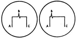
1. Perfect line up
2. Bad line up. Knob on magnetic switch needs turning anti-clockwise, or cylinder needs retarding
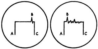
3. Bad line up. Knob on magnetic switch needs turning clockwise or cylinder needs advancing
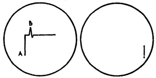
4. Indicates completely out of line. Needs re-setting on the crawl
5. Indicates that magnetic switch is faulty, or air gap too big, or machine running too slow
6. No magnetic switch working at all
7. Scanning head not working
RED NEON LIGHTS
On the power pack there are two, one of which is always on – the other will “blink” every time an alteration to register takes place on Automatic. This is known as “cycling.” The two lights on each of the output chassis “blink” when the appropriate register motor rotates either advance or retard. The lights on the control panel are duplicates of those on the output chassis.
THE GREEN “MAGIC EYES”
These are to be found on the input chassis and indicate the impulses from the cells in the scanning head. These eyes should be continually blinking whilst machine is running.
POINTS TO WATCH
If any large alterations to side register are made, possibly due to baggy-edged reels, the scanning heads should be moved the same amount as the cylinders. Especially applicable to baby machines. Check register lines to see that they are in correct sequence – in the event of their being “laid down” on the cylinders in reverse this can be overcome by turning the motor switches on the output chassis the opposite way. By doing this the register will be just as good as if the normal sequence had been followed. What must be remembered however is that advance on the control panel becomes retard and retard becomes advance with regard to manual control and error shift.
Experience has shown that the faster the press runs the greater the efficiency. It is advisable to put the control switch to the neutral position when the machine is slowing down to change reels or at any time that the machine is stopped.
FAULTS
When Autotron behaves erratically and all these previous items are known to be correct, check first that scanning head glass is clean. This often gets a smear of ink or a coating of dust which will stop unit working correctly. If still unsatisfactory, try a fresh scanning head.
NEEDLE KICKING
Check sideways lining up of scanning head, if one cell picks one line and a portion of the other it will upset register. Check distance of scanning head from web and try moving it away from or closer to the paper.
NEEDLE WAVES FROM SIDE TO SIDE
This may be dirty glass or scanning head pulled away from web after a break. Possibly it will be cylinder out of time with switch; check with oscilloscope.
REGISTER RUNNING AWAY
Usually caused by bad switch timing, especially where register line is near heavy etch. If the edge of this etch comes into the switch period, eye will pick up on the etch instead of line. Check with oscilloscope, when edge of etch will be plainly seen as another peak.
Another rather elusive cause of running away is the register line drying in, wearing out or being blown away by too much air.
POSSIBLE FAULTS
Motor “hanging on” one way after register correction may indicate a fault in output chassis – possibly a valve or faulty relay. Try spare chassis if available. If no improvement, notify office.
Indicator needle gently swinging backwards and forwards – sometimes indicates magnetic brake on register motor not working properly and so letting motor overrun.
Magnetic brake on motor working but motor not turning – sometimes indicates a blown fuse. A blown fuse indicates undue stress somewhere and the office should be notified.
STIFFNESS IN REGISTER CONTROL GEAR
Test with manual switch, if control will not move twice in same direction the motor is not powerful enough to overcome stiffness and it is usually an engineering job.
NEEDLE SWINGING IN A RHYTHMIC MANNER OVER ABOUT 10-20 THOUS.
Invariably a machine fault and pressure adjustments should be looked to especially on V.2 Vomag units. A change of scanning head often works wonders with most faults, but care must be taken to line up correctly and make sure all leads are properly tightened.
ROUTINE CHECKS
(1) Line up of magnetic switches. Check with oscilloscope.
(2) Line up laterally.
(3) Distance of scanning head from paper.
(4) Dull lamp in head. NOTE. – There is a tendency for these lamps to carbon after a few months’ use.
(5) Dirty or cracked scanning head glass.
FINALLY
The Autotron is a delicate instrument dealing with very small electrical currents and necessitates very careful and accurate setting to ensure precise registration.
Printed by Sun Printers Ltd., Watford. 750 7/52